Automotive Flow Lab Monitoring and Control System

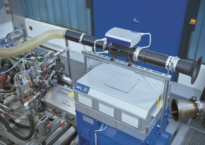
Photo Courtesy AVL not actual system
Overview
Automotive Flow lab Monitoring and Control System. A tier one automotive supplier of exhaust systems needed to upgrade their flow lab. The flow lab measured air flow through the part under test as well as various temperatures, and pressures. The software needed to monitor multiple instruments and sensors used to test the part. The software also needed to control a high speed blower, and a heater. The user interface needed to be intuitive to the operator and display and save the relevant data.
Solution
We developed custom LabVIEW software that used NI CompactRIO Hardware. CompactRIO systems provide high-performance processing capabilities, and sensor-specific conditioned I/O that make them ideal for monitoring, and control applications. Using the CompactRIO platform, we were able to monitor all the different sensors required for the test. We were also able to connect to a high performance flow meter and a controller for the blower and burner. The CompactRIO hardware allowed us the ability to add more sensors and instruments at a later time. This greatly increased the flexibility of the system.

Example of CompactRIO Controller and modules

Block Diagram of system
AVL Flow Meter
The CompactRIO enabled connectivity to an AVL Flow meter via ethernet. The AVL flow meter measured intake air mass flow with high accuracy, a large downturn ratio and fast response time.

AVL Flow Meter
Eurotherm
The CompactRIO also controlled and monitored a Eurotherm 3504 Controller via ethernet. The Eurotherm was responsible for controlling the burner that heated the air used for the test and the blower that moved the air through the device under test. The software could send blower speed and temperature setpoints to the controller.

Eurotherm Controller
Features
The Flow Lab Software controlled and monitored signals from the CompactRIO, AVL flow meter, and Eurotherm controller. All the acquired information from the hardware was displayed in a table. The row of data would turn red or yellow if the measured value was outside a limit. All the control settings were displayed in a tree control to the left side of the user interface. Dialog boxes for each acquired channel and control parameters were developed to allow the user to view and control the test. Test parameters could be saved and loaded from a file. The user could select what channels to log to a comma delimited (csv) file and at a user defined save rate. The file could then be loaded using excel for later analysis.

Main UI

Software Tree
Blower Control Dialog
The blower control dialog allowed the user to set the air flow for the test . The user could set the mass flow or variable frequency drive (VFD). The user could also ramp the air flow by time or by mass flow rate.

Limit Options
The limit options dialog allowed the user to set warning and over limit monitoring on each channel. The user could select a channel from the table to activate the limit dialog. If the measured value was outside the Low and High limit the table row of data would be red. If the measured value was outside the Low and High warning the table row of data would be yellow.

Result
The Automotive Flow lab Monitoring and Control System allowed the customer to effectively test their product. The user interface was intuitive and easy to use which lowered training costs and reduced operator error. Test data was automatically saved in a human readable format so the lab operator could feed that data back to the design team to make a higher quality product.
As a result of AST developing The Automotive Flow lab Monitoring and Control System the customer was able to quickly functionally test their product and generate data they could use to improve their design.
Let's build an application together. Contact us today
- Learn how we do a project
- Learn about Real time systems
- Learn more about NI CompactRIO
- Learn more about LabVIEW
- Learn about other test systems we have done for Automotive Customers